Air distribution is not solved by achieving total airflow alone. Diffuser location, throw, ceiling geometry, return path and temperature difference determine comfort and mixing.
Home › Knowledge Hub › HVAC & Ventilation
GLOBALTEK ENGINEERING KNOWLEDGE HUB · ACTIVITY 13
HVAC & Ventilation
HVAC design balances thermal loads, ventilation, humidity, air distribution, acoustic criteria, pressure relationships, energy performance and maintainability. Commissioning proves the installed system delivers the calculated intent.

GUIDE MAP
Read the discipline visually, then go into the engineering detail.
Every image below is activity-specific. No repeated generic placeholder sheets are used in this guide.
01
System Overview
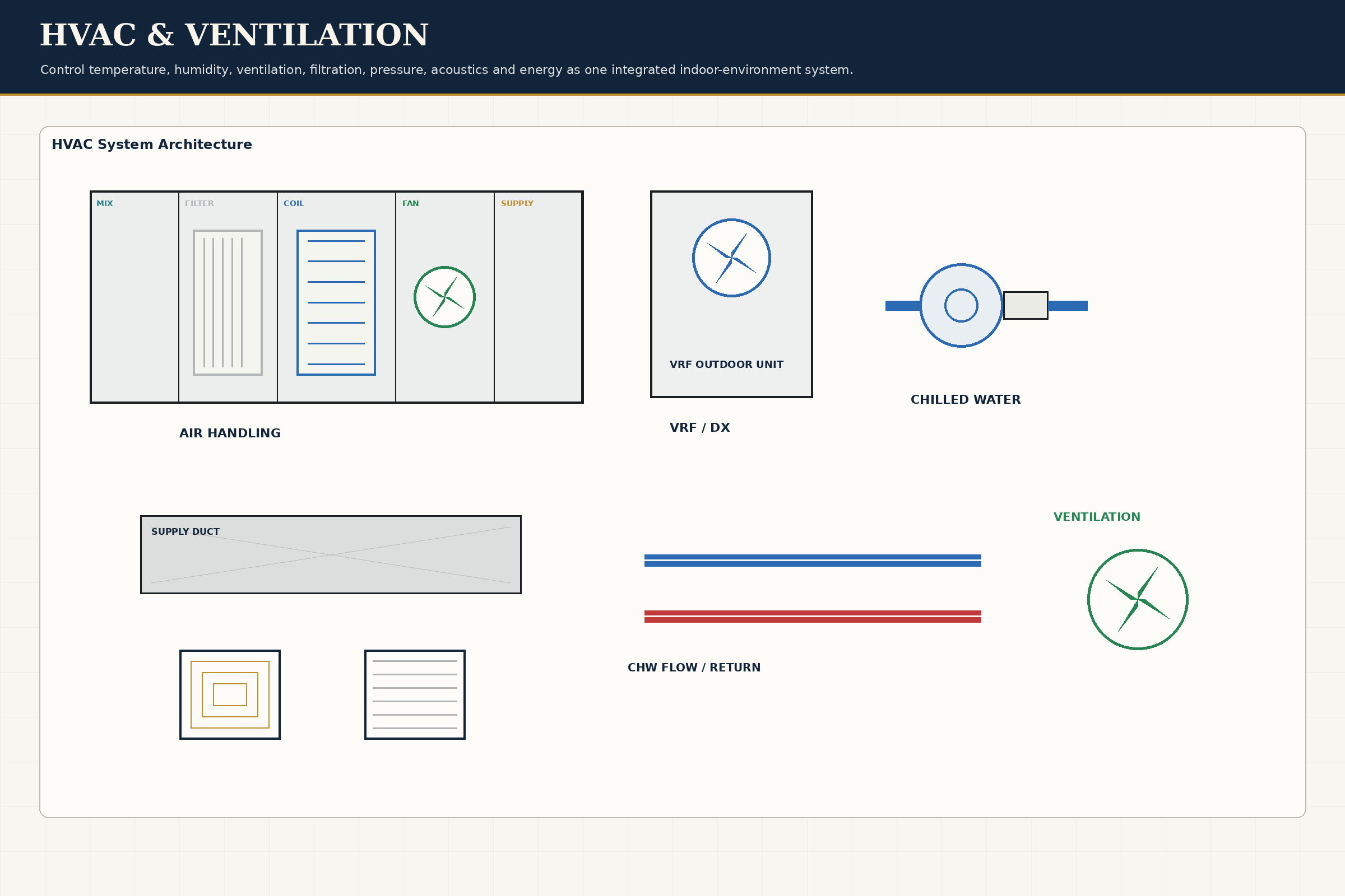
HVAC fit-out work adapts cooling and ventilation systems to the new space layout. It includes ductwork, diffusers, grilles, dampers, FCUs or VRF interfaces, chilled-water or refrigerant connections, condensate and controls.
Open section →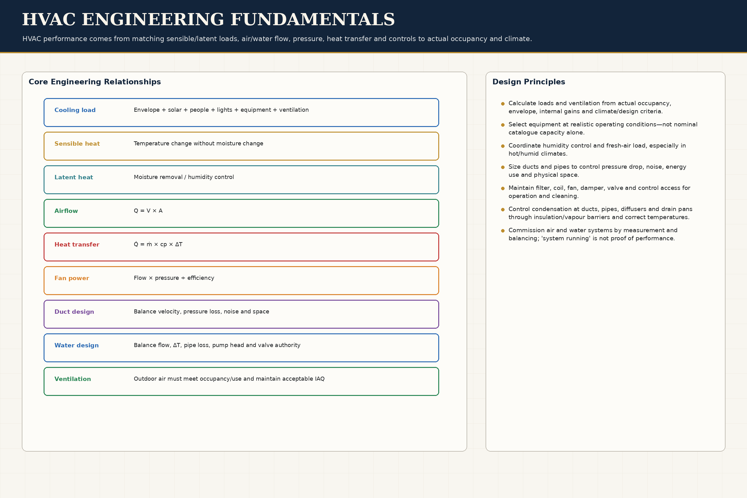
02
Engineering Fundamentals
Calculate or verify load and existing plant capacity
Open section →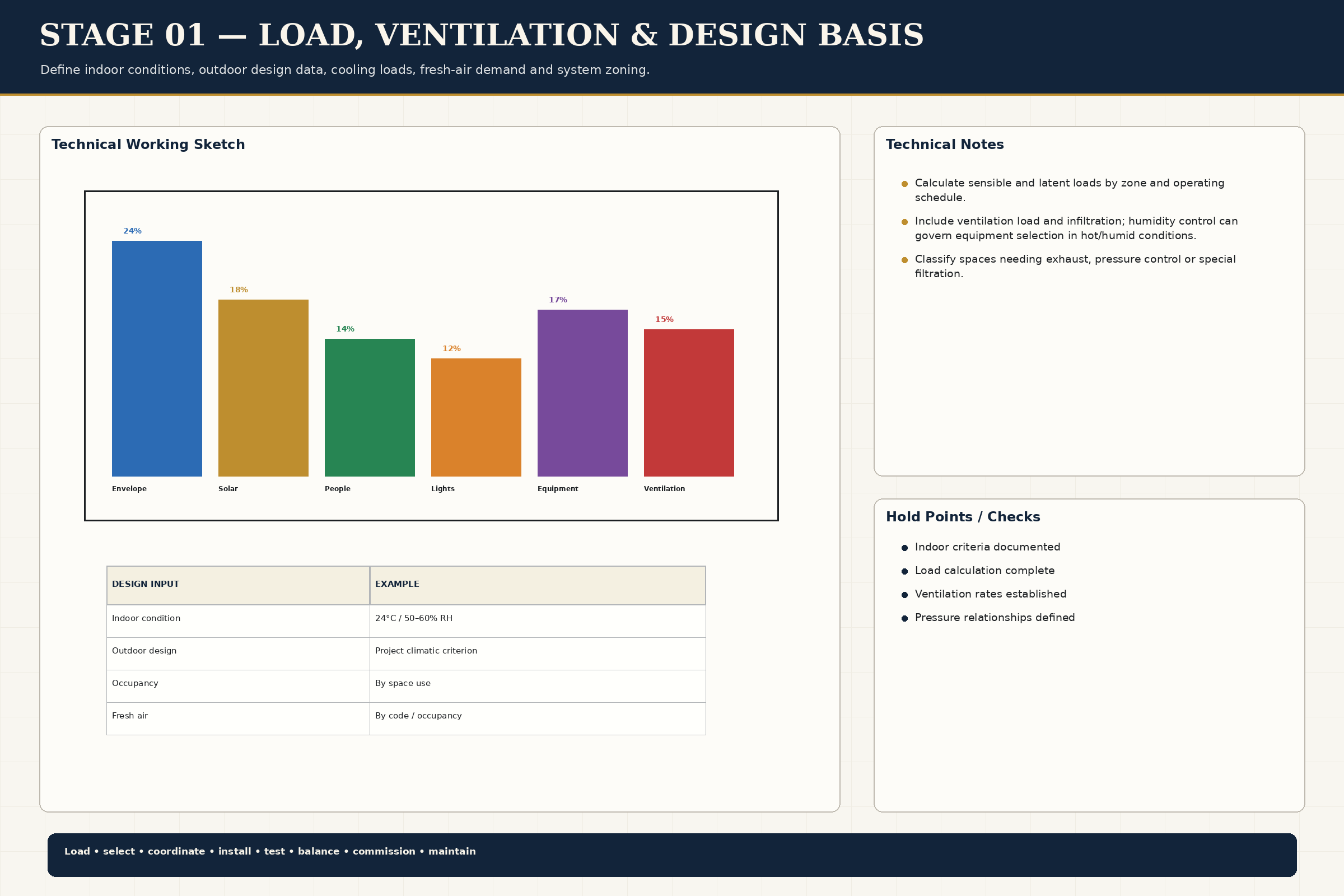
03
Execution Workflow
Confirm existing system capacity and proposed room use
Open section →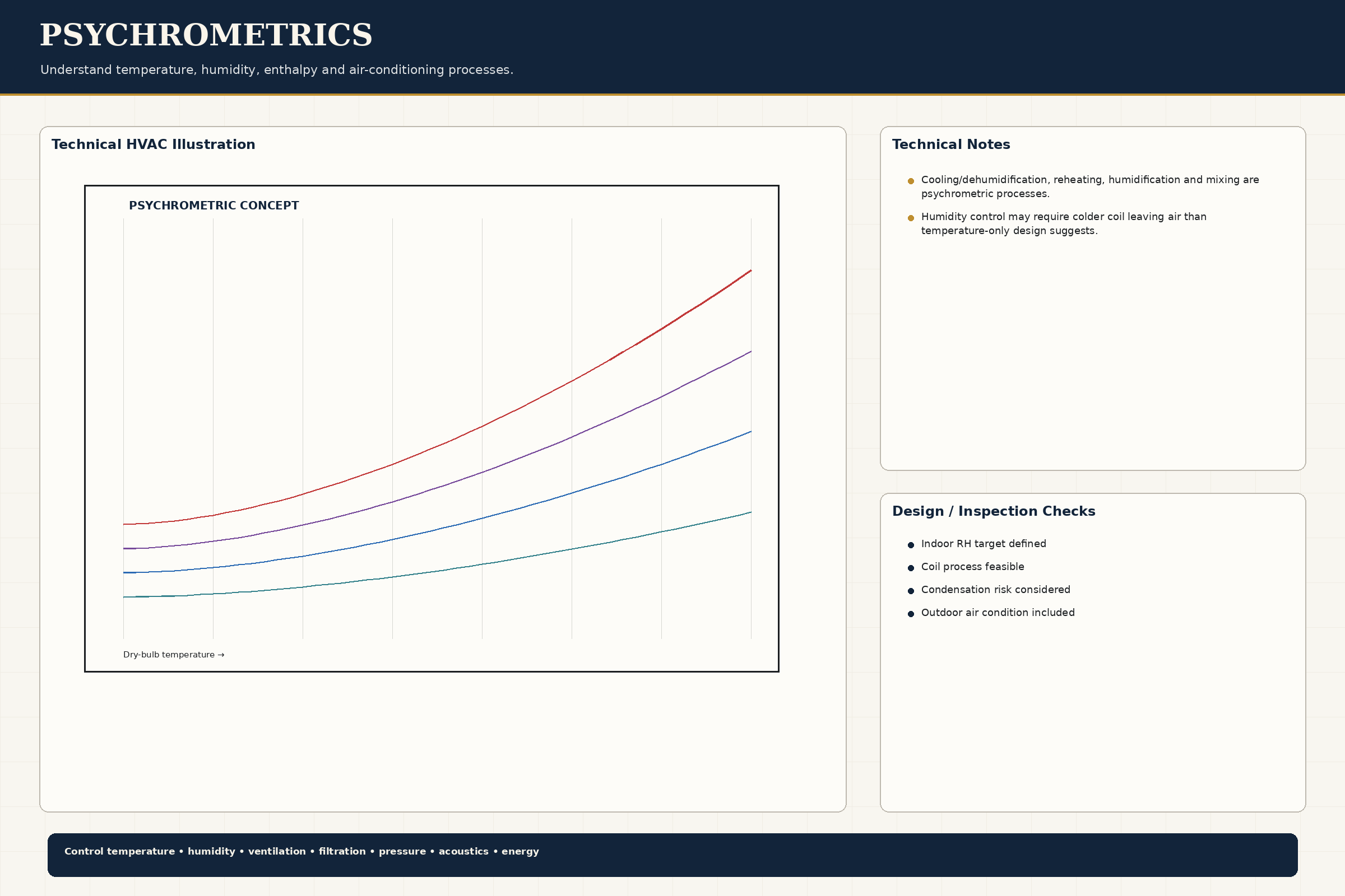
04
Technical Chapters
27 individual sub-activity drawings with discipline-specific notes and inspection controls.
Open section →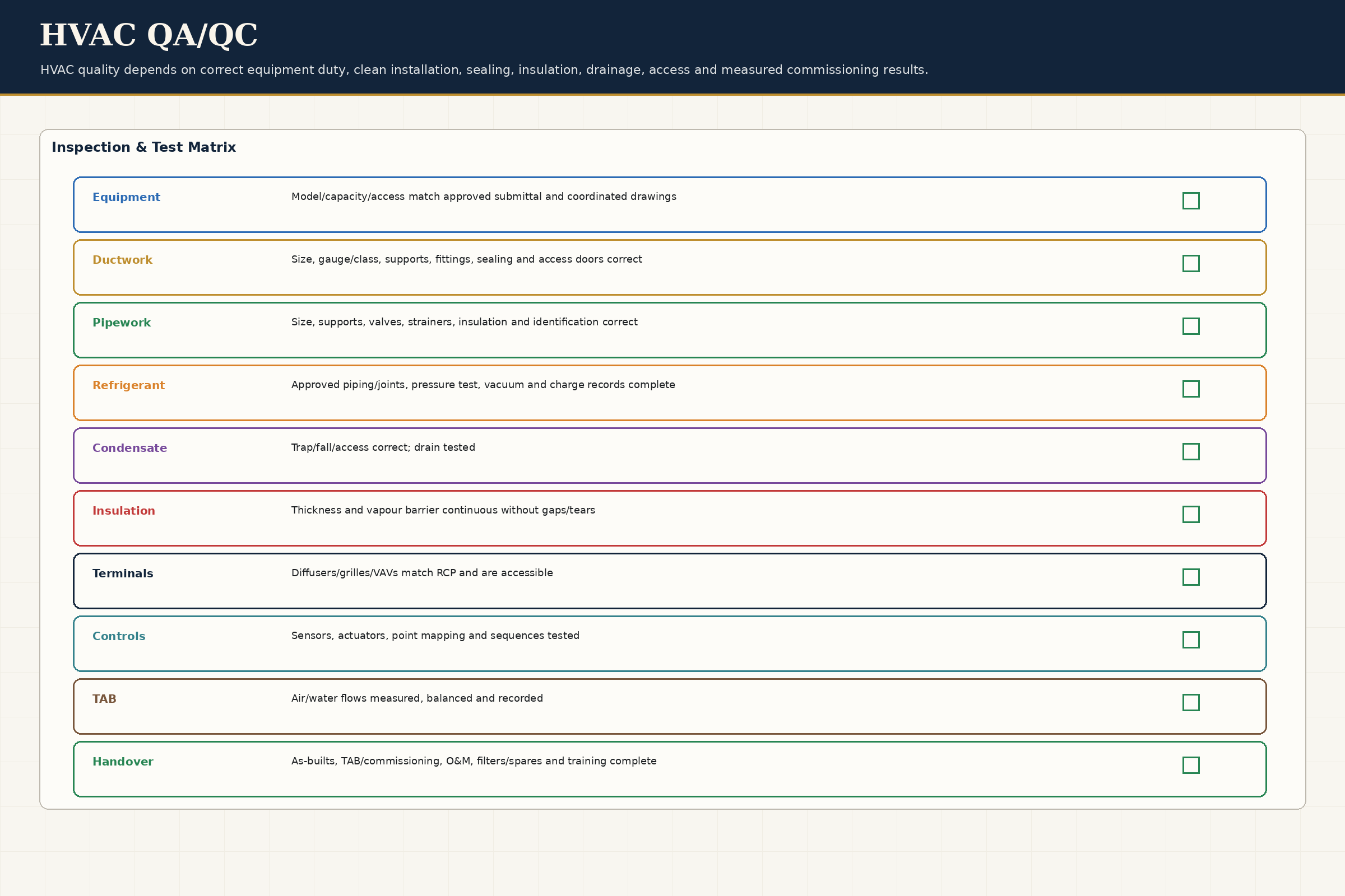
05
QA/QC
Equipment access and removal path are practical
Open section →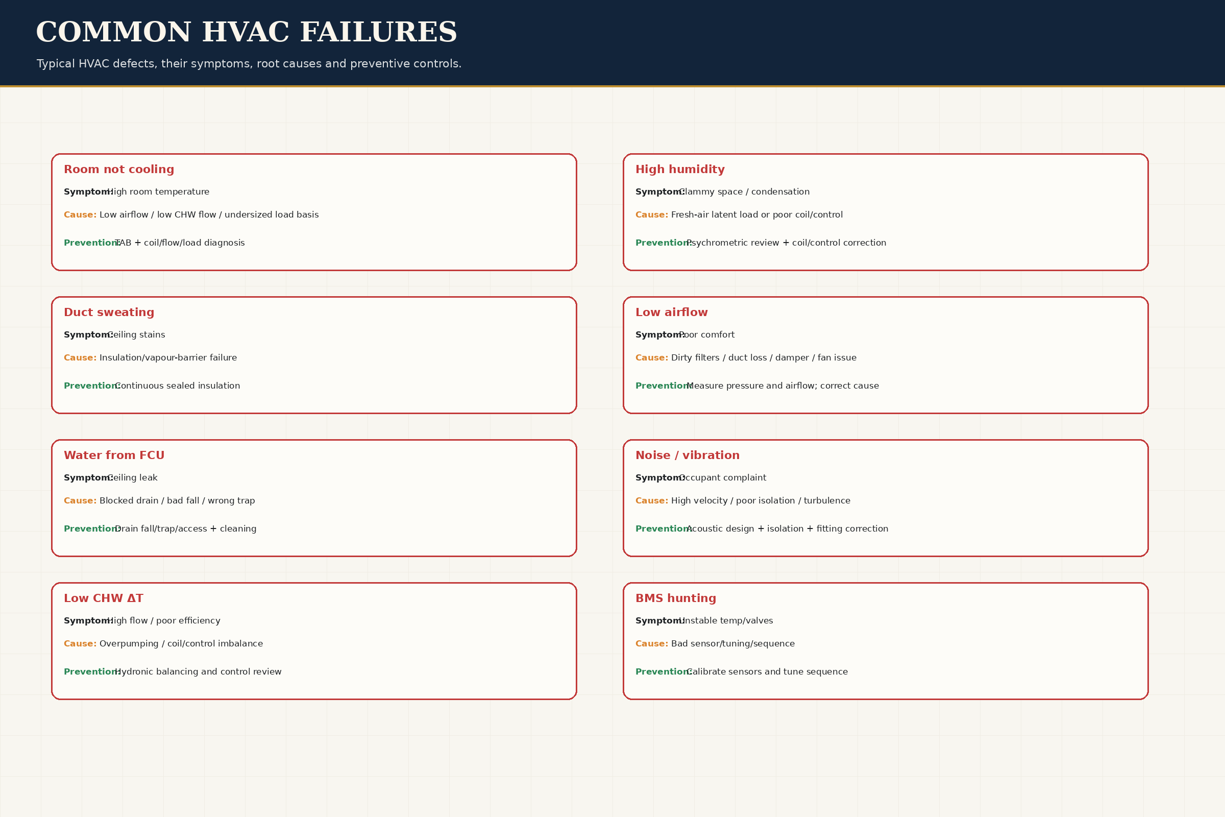
06
Failure Analysis
Oversized / undersized cooling assumptions without load check
Open section →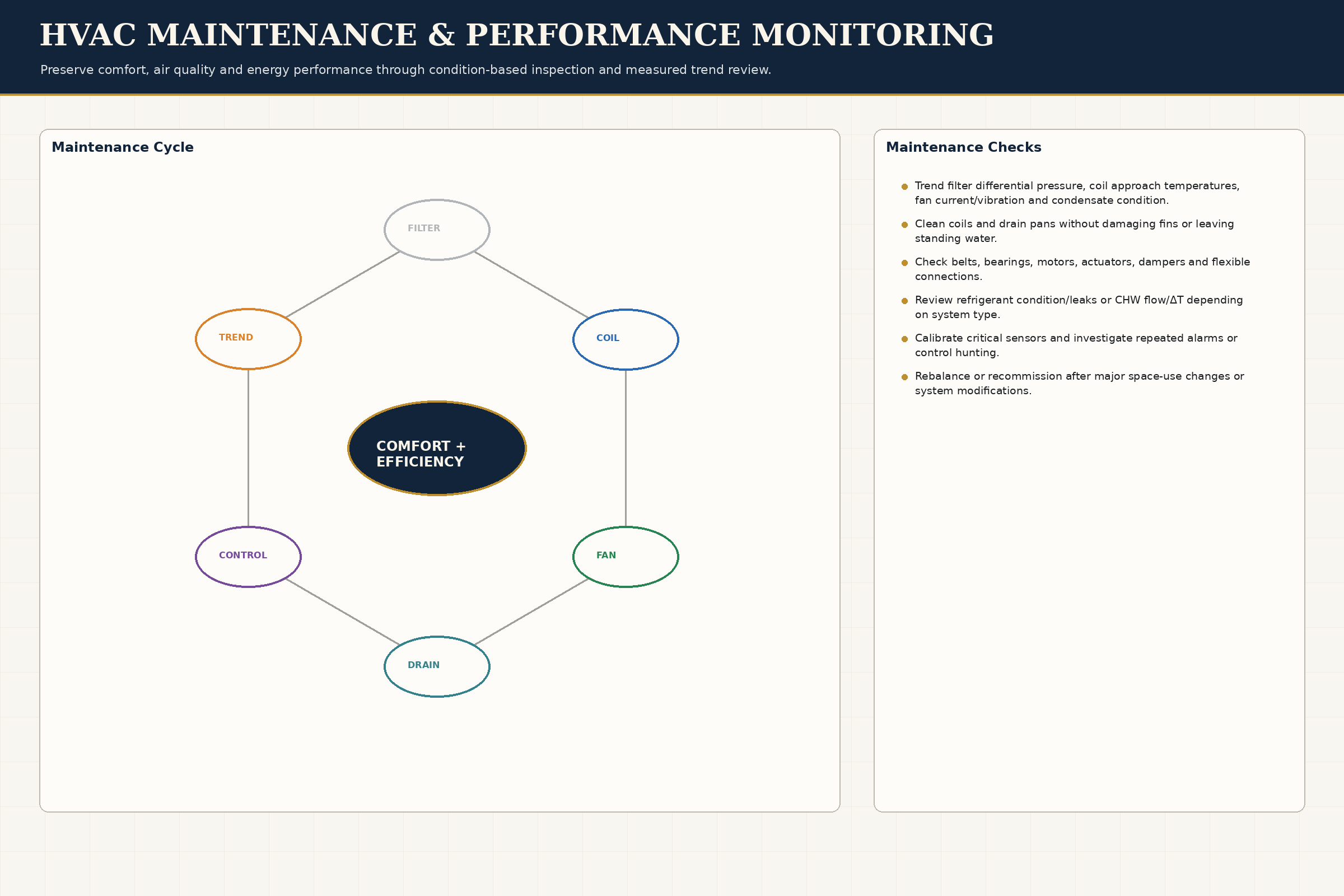
07
Maintenance
Clean / replace filters to maintain airflow and efficiency
Open section →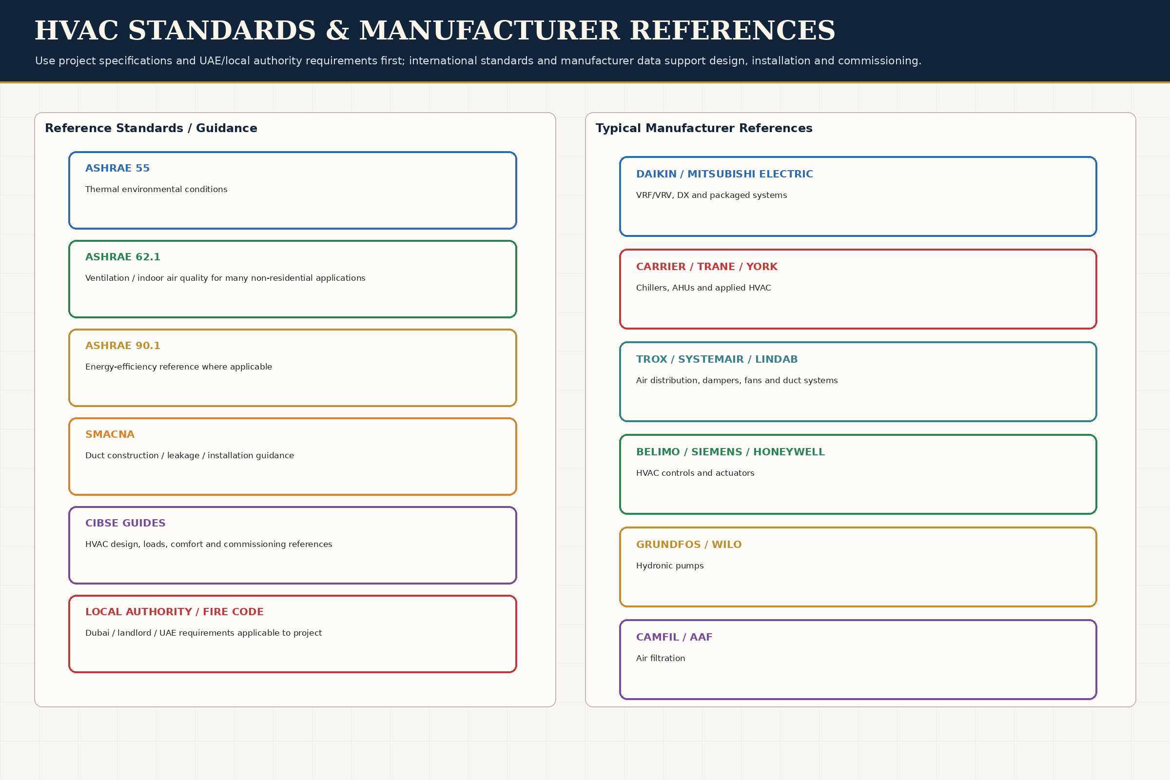
08
Standards & Brands
ASHRAE design guidance where referenced by project
Open section →01 · SYSTEM OVERVIEW
What this activity is
What this activity is
HVAC fit-out work adapts cooling and ventilation systems to the new space layout. It includes ductwork, diffusers, grilles, dampers, FCUs or VRF interfaces, chilled-water or refrigerant connections, condensate and controls.
What to expect
Expect existing cooling capacity and ventilation allowance to be checked before diffuser layouts are finalised. Air balance, noise, access to filters / FCUs and condensate management are as important as visual grille locations.
01Calculate or verify load and existing plant capacity
02Coordinate duct/pipe routes with pressure loss and access in mind
03Size air terminals for throw, noise and room geometry
04Drain condensate reliably with traps/falls where required
05Balance air and water systems using measurable devices
06Commission controls, safeties and sequences under representative modes
02 · ENGINEERING FUNDAMENTALS
Understand why the system behaves the way it does.
01
Sensible cooling Qs ≈ ṁ × cp × ΔT; total psychrometric load also includes latent moisture load
02
Airflow Q = V × A; excessive velocity raises pressure loss and noise
03
Fan power is related to airflow × pressure rise / efficiency; system resistance strongly affects operating point
Low-noise spaces require acoustic design of the HVAC path: equipment vibration isolation, duct lining/attenuation where appropriate, low terminal velocity and control of breakout/crosstalk paths.
Commissioning includes more than a test run. Verify filters, rotation, refrigerant/water conditions, controls, set-points, airflow/water balance, condensate, safeties and recorded performance.
03 · EXECUTION WORKFLOW
Six progressive stages from preparation to verified handover.
Open any plate to read the full-resolution technical notes.
01Load Ventilation Design 02Equipment Selection
 03Route Coordination
 04Installation Insulation
 05Testing Adjusting Balancing
 06Commissioning Handover
STAGE 01
Load Ventilation Design
Confirm existing system capacity and proposed room use
Engineering intent
Match approved room airflow and pressure requirements
Inspection / hold point
Equipment access and removal path are practical
Best practice
Keep filters and service panels accessible without dismantling ceilings
Failure to avoid
Oversized / undersized cooling assumptions without load check
Handover / maintenance
Clean / replace filters to maintain airflow and efficiency
STAGE 02
Equipment Selection
Resolve ducts, pipework, access, fire dampers and ceiling devices
Engineering intent
Control to limit pressure loss and noise
Inspection / hold point
Duct / pipe supports and insulation are complete
Best practice
Seal duct joints and insulation vapour barriers carefully
Failure to avoid
Blocked FCU access after ceiling completion
Handover / maintenance
Clean condensate trays / drains and inspect for microbial growth
STAGE 03
Route Coordination
Install supports, ducts, pipes, insulation and equipment
Engineering intent
Continuous vapour seal on cold surfaces to prevent condensation
Inspection / hold point
Condensate drains are tested
Best practice
Balance after architectural doors and major room conditions are complete
Failure to avoid
Condensation from damaged insulation vapour barriers
Handover / maintenance
Inspect insulation damage and condensation signs
STAGE 04
Installation Insulation
Install diffusers, grilles, thermostats, valves and actuators
Engineering intent
Filters, valves, drain trays, controls and dampers must be serviceable
Inspection / hold point
Air quantities / water flow match commissioning targets
Best practice
Locate thermostats away from direct sun / supply air / heat sources
Failure to avoid
Poor drainage causing overflow and ceiling staining
Handover / maintenance
Check belts / bearings / fans where applicable
STAGE 05
Testing Adjusting Balancing
Leak check, flush where required, balance air / water and verify drainage
Engineering intent
Coordinate with room geometry and avoid drafts / dead zones
Inspection / hold point
Controls and sensors respond correctly
Best practice
Coordinate diffuser pattern with lighting and occupancy
Failure to avoid
Noise from excessive air velocity or rigid vibration paths
Handover / maintenance
Verify thermostat / control calibration when comfort complaints recur
STAGE 06
Commissioning Handover
Confirm temperatures, control sequences, alarms and user operation
Engineering intent
Provide reliable fall, trap and cleaning access
Inspection / hold point
Noise / vibration are acceptable in occupied conditions
Best practice
Retain balancing damper positions and commissioning results
Failure to avoid
Skipping final air balance after layout changes
Handover / maintenance
Rebalance after significant partition or occupancy changes
04 · TECHNICAL CHAPTERS
27 detailed sub-activities for HVAC & Ventilation.
The file naming and page mapping are one-to-one: each technical subject has its own individual high-resolution image.
01Psychrometrics02Cooling Load Calculation03Ventilation Iaq04Air Handling Units05Fan Coil Units06VRF Vrv Systems07Chilled Water Systems08Pumps Valves Controls09Refrigerant Piping10Duct Sizing11Duct Fittings Transitions12Duct Sealing Leakage13Duct Insulation Vapour Barrier14Diffusers Grilles15VAV Cav Terminals16Fresh Air Make Up Air17Exhaust Kitchen Toilet18Smoke Control Pressurisation19Condensate Drainage20Filtration Air Cleaning21Controls BMS22Acoustic Vibration Control23Equipment Access Maintainability24Testing Adjusting Balancing25Hydronic Balancing26Energy Efficiency Optimisation27Energy Recovery
TECHNICAL CHAPTER 01
Psychrometrics
Psychrometrics: Coordinate heat load, equipment selection, air/water flow, duct/pipe sizing, insulation, vibration, controls, access, balancing, acoustics and commissioning.
Design intent
Define the performance and construction intent for psychrometrics before fabrication or installation. Read the drawing together with the approved project specification, manufacturer data and adjoining details.
Coordination
Coordinate heat load, equipment selection, air/water flow, duct/pipe sizing, insulation, vibration, controls, access, balancing, acoustics and commissioning.
Inspection / QA
Equipment access and removal path are practical
Failure to avoid
Oversized / undersized cooling assumptions without load check
Maintenance / long-term performance
Clean / replace filters to maintain airflow and efficiency

TECHNICAL CHAPTER 02
Cooling Load Calculation
Cooling Load Calculation: Coordinate heat load, equipment selection, air/water flow, duct/pipe sizing, insulation, vibration, controls, access, balancing, acoustics and commissioning.
Design intent
Define the performance and construction intent for cooling load calculation before fabrication or installation. Read the drawing together with the approved project specification, manufacturer data and adjoining details.
Coordination
Coordinate heat load, equipment selection, air/water flow, duct/pipe sizing, insulation, vibration, controls, access, balancing, acoustics and commissioning.
Inspection / QA
Duct / pipe supports and insulation are complete
Failure to avoid
Blocked FCU access after ceiling completion
Maintenance / long-term performance
Clean condensate trays / drains and inspect for microbial growth

TECHNICAL CHAPTER 03
Ventilation Iaq
Ventilation Iaq: Coordinate heat load, equipment selection, air/water flow, duct/pipe sizing, insulation, vibration, controls, access, balancing, acoustics and commissioning.
Design intent
Define the performance and construction intent for ventilation iaq before fabrication or installation. Read the drawing together with the approved project specification, manufacturer data and adjoining details.
Coordination
Coordinate heat load, equipment selection, air/water flow, duct/pipe sizing, insulation, vibration, controls, access, balancing, acoustics and commissioning.
Inspection / QA
Condensate drains are tested
Failure to avoid
Condensation from damaged insulation vapour barriers
Maintenance / long-term performance
Inspect insulation damage and condensation signs

TECHNICAL CHAPTER 04
Air Handling Units
Air Handling Units: Coordinate heat load, equipment selection, air/water flow, duct/pipe sizing, insulation, vibration, controls, access, balancing, acoustics and commissioning.
Design intent
Define the performance and construction intent for air handling units before fabrication or installation. Read the drawing together with the approved project specification, manufacturer data and adjoining details.
Coordination
Coordinate heat load, equipment selection, air/water flow, duct/pipe sizing, insulation, vibration, controls, access, balancing, acoustics and commissioning.
Inspection / QA
Air quantities / water flow match commissioning targets
Failure to avoid
Poor drainage causing overflow and ceiling staining
Maintenance / long-term performance
Check belts / bearings / fans where applicable

TECHNICAL CHAPTER 05
Fan Coil Units
Fan Coil Units: Coordinate heat load, equipment selection, air/water flow, duct/pipe sizing, insulation, vibration, controls, access, balancing, acoustics and commissioning.
Design intent
Define the performance and construction intent for fan coil units before fabrication or installation. Read the drawing together with the approved project specification, manufacturer data and adjoining details.
Coordination
Coordinate heat load, equipment selection, air/water flow, duct/pipe sizing, insulation, vibration, controls, access, balancing, acoustics and commissioning.
Inspection / QA
Controls and sensors respond correctly
Failure to avoid
Noise from excessive air velocity or rigid vibration paths
Maintenance / long-term performance
Verify thermostat / control calibration when comfort complaints recur

TECHNICAL CHAPTER 06
VRF Vrv Systems
VRF Vrv Systems: Coordinate heat load, equipment selection, air/water flow, duct/pipe sizing, insulation, vibration, controls, access, balancing, acoustics and commissioning.
Design intent
Define the performance and construction intent for vrf vrv systems before fabrication or installation. Read the drawing together with the approved project specification, manufacturer data and adjoining details.
Coordination
Coordinate heat load, equipment selection, air/water flow, duct/pipe sizing, insulation, vibration, controls, access, balancing, acoustics and commissioning.
Inspection / QA
Noise / vibration are acceptable in occupied conditions
Failure to avoid
Skipping final air balance after layout changes
Maintenance / long-term performance
Rebalance after significant partition or occupancy changes

TECHNICAL CHAPTER 07
Chilled Water Systems
Chilled Water Systems: Coordinate heat load, equipment selection, air/water flow, duct/pipe sizing, insulation, vibration, controls, access, balancing, acoustics and commissioning.
Design intent
Define the performance and construction intent for chilled water systems before fabrication or installation. Read the drawing together with the approved project specification, manufacturer data and adjoining details.
Coordination
Coordinate heat load, equipment selection, air/water flow, duct/pipe sizing, insulation, vibration, controls, access, balancing, acoustics and commissioning.
Inspection / QA
Equipment access and removal path are practical
Failure to avoid
Oversized / undersized cooling assumptions without load check
Maintenance / long-term performance
Clean / replace filters to maintain airflow and efficiency

TECHNICAL CHAPTER 08
Pumps Valves Controls
Pumps Valves Controls: Coordinate heat load, equipment selection, air/water flow, duct/pipe sizing, insulation, vibration, controls, access, balancing, acoustics and commissioning.
Design intent
Define the performance and construction intent for pumps valves controls before fabrication or installation. Read the drawing together with the approved project specification, manufacturer data and adjoining details.
Coordination
Coordinate heat load, equipment selection, air/water flow, duct/pipe sizing, insulation, vibration, controls, access, balancing, acoustics and commissioning.
Inspection / QA
Duct / pipe supports and insulation are complete
Failure to avoid
Blocked FCU access after ceiling completion
Maintenance / long-term performance
Clean condensate trays / drains and inspect for microbial growth

TECHNICAL CHAPTER 09
Refrigerant Piping
Refrigerant Piping: Coordinate heat load, equipment selection, air/water flow, duct/pipe sizing, insulation, vibration, controls, access, balancing, acoustics and commissioning.
Design intent
Define the performance and construction intent for refrigerant piping before fabrication or installation. Read the drawing together with the approved project specification, manufacturer data and adjoining details.
Coordination
Coordinate heat load, equipment selection, air/water flow, duct/pipe sizing, insulation, vibration, controls, access, balancing, acoustics and commissioning.
Inspection / QA
Condensate drains are tested
Failure to avoid
Condensation from damaged insulation vapour barriers
Maintenance / long-term performance
Inspect insulation damage and condensation signs

TECHNICAL CHAPTER 10
Duct Sizing
Duct Sizing: Coordinate heat load, equipment selection, air/water flow, duct/pipe sizing, insulation, vibration, controls, access, balancing, acoustics and commissioning.
Design intent
Define the performance and construction intent for duct sizing before fabrication or installation. Read the drawing together with the approved project specification, manufacturer data and adjoining details.
Coordination
Coordinate heat load, equipment selection, air/water flow, duct/pipe sizing, insulation, vibration, controls, access, balancing, acoustics and commissioning.
Inspection / QA
Air quantities / water flow match commissioning targets
Failure to avoid
Poor drainage causing overflow and ceiling staining
Maintenance / long-term performance
Check belts / bearings / fans where applicable

TECHNICAL CHAPTER 11
Duct Fittings Transitions
Duct Fittings Transitions: Coordinate heat load, equipment selection, air/water flow, duct/pipe sizing, insulation, vibration, controls, access, balancing, acoustics and commissioning.
Design intent
Define the performance and construction intent for duct fittings transitions before fabrication or installation. Read the drawing together with the approved project specification, manufacturer data and adjoining details.
Coordination
Coordinate heat load, equipment selection, air/water flow, duct/pipe sizing, insulation, vibration, controls, access, balancing, acoustics and commissioning.
Inspection / QA
Controls and sensors respond correctly
Failure to avoid
Noise from excessive air velocity or rigid vibration paths
Maintenance / long-term performance
Verify thermostat / control calibration when comfort complaints recur

TECHNICAL CHAPTER 12
Duct Sealing Leakage
Duct Sealing Leakage: Coordinate heat load, equipment selection, air/water flow, duct/pipe sizing, insulation, vibration, controls, access, balancing, acoustics and commissioning.
Design intent
Define the performance and construction intent for duct sealing leakage before fabrication or installation. Read the drawing together with the approved project specification, manufacturer data and adjoining details.
Coordination
Coordinate heat load, equipment selection, air/water flow, duct/pipe sizing, insulation, vibration, controls, access, balancing, acoustics and commissioning.
Inspection / QA
Noise / vibration are acceptable in occupied conditions
Failure to avoid
Skipping final air balance after layout changes
Maintenance / long-term performance
Rebalance after significant partition or occupancy changes

TECHNICAL CHAPTER 13
Duct Insulation Vapour Barrier
Duct Insulation Vapour Barrier: Coordinate heat load, equipment selection, air/water flow, duct/pipe sizing, insulation, vibration, controls, access, balancing, acoustics and commissioning.
Design intent
Define the performance and construction intent for duct insulation vapour barrier before fabrication or installation. Read the drawing together with the approved project specification, manufacturer data and adjoining details.
Coordination
Coordinate heat load, equipment selection, air/water flow, duct/pipe sizing, insulation, vibration, controls, access, balancing, acoustics and commissioning.
Inspection / QA
Equipment access and removal path are practical
Failure to avoid
Oversized / undersized cooling assumptions without load check
Maintenance / long-term performance
Clean / replace filters to maintain airflow and efficiency

TECHNICAL CHAPTER 14
Diffusers Grilles
Diffusers Grilles: Coordinate heat load, equipment selection, air/water flow, duct/pipe sizing, insulation, vibration, controls, access, balancing, acoustics and commissioning.
Design intent
Define the performance and construction intent for diffusers grilles before fabrication or installation. Read the drawing together with the approved project specification, manufacturer data and adjoining details.
Coordination
Coordinate heat load, equipment selection, air/water flow, duct/pipe sizing, insulation, vibration, controls, access, balancing, acoustics and commissioning.
Inspection / QA
Duct / pipe supports and insulation are complete
Failure to avoid
Blocked FCU access after ceiling completion
Maintenance / long-term performance
Clean condensate trays / drains and inspect for microbial growth

TECHNICAL CHAPTER 15
VAV Cav Terminals
VAV Cav Terminals: Coordinate heat load, equipment selection, air/water flow, duct/pipe sizing, insulation, vibration, controls, access, balancing, acoustics and commissioning.
Design intent
Define the performance and construction intent for vav cav terminals before fabrication or installation. Read the drawing together with the approved project specification, manufacturer data and adjoining details.
Coordination
Coordinate heat load, equipment selection, air/water flow, duct/pipe sizing, insulation, vibration, controls, access, balancing, acoustics and commissioning.
Inspection / QA
Condensate drains are tested
Failure to avoid
Condensation from damaged insulation vapour barriers
Maintenance / long-term performance
Inspect insulation damage and condensation signs

TECHNICAL CHAPTER 16
Fresh Air Make Up Air
Fresh Air Make Up Air: Coordinate heat load, equipment selection, air/water flow, duct/pipe sizing, insulation, vibration, controls, access, balancing, acoustics and commissioning.
Design intent
Define the performance and construction intent for fresh air make up air before fabrication or installation. Read the drawing together with the approved project specification, manufacturer data and adjoining details.
Coordination
Coordinate heat load, equipment selection, air/water flow, duct/pipe sizing, insulation, vibration, controls, access, balancing, acoustics and commissioning.
Inspection / QA
Air quantities / water flow match commissioning targets
Failure to avoid
Poor drainage causing overflow and ceiling staining
Maintenance / long-term performance
Check belts / bearings / fans where applicable

TECHNICAL CHAPTER 17
Exhaust Kitchen Toilet
Exhaust Kitchen Toilet: Coordinate heat load, equipment selection, air/water flow, duct/pipe sizing, insulation, vibration, controls, access, balancing, acoustics and commissioning.
Design intent
Define the performance and construction intent for exhaust kitchen toilet before fabrication or installation. Read the drawing together with the approved project specification, manufacturer data and adjoining details.
Coordination
Coordinate heat load, equipment selection, air/water flow, duct/pipe sizing, insulation, vibration, controls, access, balancing, acoustics and commissioning.
Inspection / QA
Controls and sensors respond correctly
Failure to avoid
Noise from excessive air velocity or rigid vibration paths
Maintenance / long-term performance
Verify thermostat / control calibration when comfort complaints recur

TECHNICAL CHAPTER 18
Smoke Control Pressurisation
Smoke Control Pressurisation: Coordinate heat load, equipment selection, air/water flow, duct/pipe sizing, insulation, vibration, controls, access, balancing, acoustics and commissioning.
Design intent
Define the performance and construction intent for smoke control pressurisation before fabrication or installation. Read the drawing together with the approved project specification, manufacturer data and adjoining details.
Coordination
Coordinate heat load, equipment selection, air/water flow, duct/pipe sizing, insulation, vibration, controls, access, balancing, acoustics and commissioning.
Inspection / QA
Noise / vibration are acceptable in occupied conditions
Failure to avoid
Skipping final air balance after layout changes
Maintenance / long-term performance
Rebalance after significant partition or occupancy changes

TECHNICAL CHAPTER 19
Condensate Drainage
Condensate Drainage: Coordinate heat load, equipment selection, air/water flow, duct/pipe sizing, insulation, vibration, controls, access, balancing, acoustics and commissioning.
Design intent
Define the performance and construction intent for condensate drainage before fabrication or installation. Read the drawing together with the approved project specification, manufacturer data and adjoining details.
Coordination
Coordinate heat load, equipment selection, air/water flow, duct/pipe sizing, insulation, vibration, controls, access, balancing, acoustics and commissioning.
Inspection / QA
Equipment access and removal path are practical
Failure to avoid
Oversized / undersized cooling assumptions without load check
Maintenance / long-term performance
Clean / replace filters to maintain airflow and efficiency

TECHNICAL CHAPTER 20
Filtration Air Cleaning
Filtration Air Cleaning: Coordinate heat load, equipment selection, air/water flow, duct/pipe sizing, insulation, vibration, controls, access, balancing, acoustics and commissioning.
Design intent
Define the performance and construction intent for filtration air cleaning before fabrication or installation. Read the drawing together with the approved project specification, manufacturer data and adjoining details.
Coordination
Coordinate heat load, equipment selection, air/water flow, duct/pipe sizing, insulation, vibration, controls, access, balancing, acoustics and commissioning.
Inspection / QA
Duct / pipe supports and insulation are complete
Failure to avoid
Blocked FCU access after ceiling completion
Maintenance / long-term performance
Clean condensate trays / drains and inspect for microbial growth

TECHNICAL CHAPTER 21
Controls BMS
Controls BMS: Coordinate heat load, equipment selection, air/water flow, duct/pipe sizing, insulation, vibration, controls, access, balancing, acoustics and commissioning.
Design intent
Define the performance and construction intent for controls bms before fabrication or installation. Read the drawing together with the approved project specification, manufacturer data and adjoining details.
Coordination
Coordinate heat load, equipment selection, air/water flow, duct/pipe sizing, insulation, vibration, controls, access, balancing, acoustics and commissioning.
Inspection / QA
Condensate drains are tested
Failure to avoid
Condensation from damaged insulation vapour barriers
Maintenance / long-term performance
Inspect insulation damage and condensation signs

TECHNICAL CHAPTER 22
Acoustic Vibration Control
Acoustic Vibration Control: Coordinate heat load, equipment selection, air/water flow, duct/pipe sizing, insulation, vibration, controls, access, balancing, acoustics and commissioning.
Design intent
Define the performance and construction intent for acoustic vibration control before fabrication or installation. Read the drawing together with the approved project specification, manufacturer data and adjoining details.
Coordination
Coordinate heat load, equipment selection, air/water flow, duct/pipe sizing, insulation, vibration, controls, access, balancing, acoustics and commissioning.
Inspection / QA
Air quantities / water flow match commissioning targets
Failure to avoid
Poor drainage causing overflow and ceiling staining
Maintenance / long-term performance
Check belts / bearings / fans where applicable

TECHNICAL CHAPTER 23
Equipment Access Maintainability
Equipment Access Maintainability: Coordinate heat load, equipment selection, air/water flow, duct/pipe sizing, insulation, vibration, controls, access, balancing, acoustics and commissioning.
Design intent
Define the performance and construction intent for equipment access maintainability before fabrication or installation. Read the drawing together with the approved project specification, manufacturer data and adjoining details.
Coordination
Coordinate heat load, equipment selection, air/water flow, duct/pipe sizing, insulation, vibration, controls, access, balancing, acoustics and commissioning.
Inspection / QA
Controls and sensors respond correctly
Failure to avoid
Noise from excessive air velocity or rigid vibration paths
Maintenance / long-term performance
Verify thermostat / control calibration when comfort complaints recur

TECHNICAL CHAPTER 24
Testing Adjusting Balancing
Testing Adjusting Balancing: Coordinate heat load, equipment selection, air/water flow, duct/pipe sizing, insulation, vibration, controls, access, balancing, acoustics and commissioning.
Design intent
Define the performance and construction intent for testing adjusting balancing before fabrication or installation. Read the drawing together with the approved project specification, manufacturer data and adjoining details.
Coordination
Coordinate heat load, equipment selection, air/water flow, duct/pipe sizing, insulation, vibration, controls, access, balancing, acoustics and commissioning.
Inspection / QA
Noise / vibration are acceptable in occupied conditions
Failure to avoid
Skipping final air balance after layout changes
Maintenance / long-term performance
Rebalance after significant partition or occupancy changes

TECHNICAL CHAPTER 25
Hydronic Balancing
Hydronic Balancing: Coordinate heat load, equipment selection, air/water flow, duct/pipe sizing, insulation, vibration, controls, access, balancing, acoustics and commissioning.
Design intent
Define the performance and construction intent for hydronic balancing before fabrication or installation. Read the drawing together with the approved project specification, manufacturer data and adjoining details.
Coordination
Coordinate heat load, equipment selection, air/water flow, duct/pipe sizing, insulation, vibration, controls, access, balancing, acoustics and commissioning.
Inspection / QA
Equipment access and removal path are practical
Failure to avoid
Oversized / undersized cooling assumptions without load check
Maintenance / long-term performance
Clean / replace filters to maintain airflow and efficiency

TECHNICAL CHAPTER 26
Energy Efficiency Optimisation
Energy Efficiency Optimisation: Coordinate heat load, equipment selection, air/water flow, duct/pipe sizing, insulation, vibration, controls, access, balancing, acoustics and commissioning.
Design intent
Define the performance and construction intent for energy efficiency optimisation before fabrication or installation. Read the drawing together with the approved project specification, manufacturer data and adjoining details.
Coordination
Coordinate heat load, equipment selection, air/water flow, duct/pipe sizing, insulation, vibration, controls, access, balancing, acoustics and commissioning.
Inspection / QA
Duct / pipe supports and insulation are complete
Failure to avoid
Blocked FCU access after ceiling completion
Maintenance / long-term performance
Clean condensate trays / drains and inspect for microbial growth

TECHNICAL CHAPTER 27
Energy Recovery
Energy Recovery: Coordinate heat load, equipment selection, air/water flow, duct/pipe sizing, insulation, vibration, controls, access, balancing, acoustics and commissioning.
Design intent
Define the performance and construction intent for energy recovery before fabrication or installation. Read the drawing together with the approved project specification, manufacturer data and adjoining details.
Coordination
Coordinate heat load, equipment selection, air/water flow, duct/pipe sizing, insulation, vibration, controls, access, balancing, acoustics and commissioning.
Inspection / QA
Condensate drains are tested
Failure to avoid
Condensation from damaged insulation vapour barriers
Maintenance / long-term performance
Inspect insulation damage and condensation signs
05 · QA/QC
Inspect before concealment and before handover.
01Equipment access and removal path are practical
02Duct / pipe supports and insulation are complete
03Condensate drains are tested
04Air quantities / water flow match commissioning targets
05Controls and sensors respond correctly
06Noise / vibration are acceptable in occupied conditions
06 · COMMON FAILURES
Recognise the failure mechanism—not only the visible defect.
Failures to avoid
×Oversized / undersized cooling assumptions without load check
×Blocked FCU access after ceiling completion
×Condensation from damaged insulation vapour barriers
×Poor drainage causing overflow and ceiling staining
×Noise from excessive air velocity or rigid vibration paths
×Skipping final air balance after layout changes
07 · MAINTENANCE & AFTERCARE
Design for access, repair and long-term performance.
Maintenance controls
✓Clean / replace filters to maintain airflow and efficiency
✓Clean condensate trays / drains and inspect for microbial growth
✓Inspect insulation damage and condensation signs
✓Check belts / bearings / fans where applicable
✓Verify thermostat / control calibration when comfort complaints recur
✓Rebalance after significant partition or occupancy changes
08 · STANDARDS & MANUFACTURER REFERENCES
Use the latest approved project documents and tested systems.
• ASHRAE design guidance where referenced by project
• SMACNA duct construction / support practices where specified
• Current building / authority ventilation and energy requirements
• Manufacturer instructions for FCUs, VRF equipment, valves and controls
• Project acoustic, insulation and fire-smoke damper requirements
• Approved testing, adjusting and balancing procedures
Technical guidance is educational and indicative. Final design, dimensions, materials, installation details and acceptance criteria must follow the approved project documents, manufacturer instructions and the latest requirements of the relevant UAE authority, landlord, consultant and specialist engineer.
09 · COMPLETE IMAGE LIBRARY
40 high-resolution visuals assigned to this activity.
Each file remains separate and is mapped directly to its relevant section. Click any image to inspect it at full resolution.
HeroOverviewFundamentalsQA/QCFailuresMaintenanceStandards & Brands Stage 01 · Load Ventilation DesignStage 02 · Equipment SelectionStage 03 · Route CoordinationStage 04 · Installation InsulationStage 05 · Testing Adjusting BalancingStage 06 · Commissioning Handover 01 · Psychrometrics02 · Cooling Load Calculation03 · Ventilation Iaq04 · Air Handling Units05 · Fan Coil Units06 · VRF Vrv Systems07 · Chilled Water Systems08 · Pumps Valves Controls09 · Refrigerant Piping10 · Duct Sizing11 · Duct Fittings Transitions12 · Duct Sealing Leakage13 · Duct Insulation Vapour Barrier14 · Diffusers Grilles15 · VAV Cav Terminals16 · Fresh Air Make Up Air17 · Exhaust Kitchen Toilet18 · Smoke Control Pressurisation19 · Condensate Drainage20 · Filtration Air Cleaning21 · Controls BMS22 · Acoustic Vibration Control23 · Equipment Access Maintainability24 · Testing Adjusting Balancing25 · Hydronic Balancing26 · Energy Efficiency Optimisation27 · Energy Recovery